Example Quarter wave plate thickness calculator #2: INPUTS: Wavelength = 590 nm, n0 = 1.66, ne = 1.49 OUTPUTS: Thickness = 867.65. Quarter wave plate thickness formula or equation. Following quarter wave plate thickness formula is used for this calculator#2. Refer difference between half wave plate vs quarter wave plate.
The input impedance of a line an odd multiple of λ/4 long is
- Bass Reflex Box Calculator Onken Bass Reflex Calculator Calculate Speed of Sound in fibrous material Calculate the Required Amplifier Output Power Calculate Back Loaded Exponential Horn Calculate Tapered Quarter - Wave Tube Calculate Baffle Diffraction Loss.
- We can provide you with comprehensive Subwoofer Box Calculator for online creating a high performance subwoofer enclosure. Build a ported box, sealed box for your low-frequency speaker. Make a subwoofer enclosure plan. Calculate a speaker box volume, port length and other parameters without getting confused in formulas.
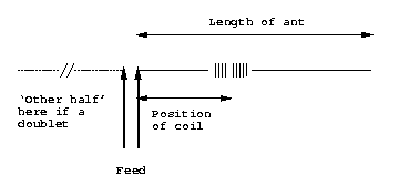
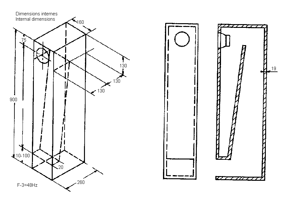
The basic formula for determining the length of a center fed, half-wave wire Dipole or Inverted Vee antenna is. 468 ÷ freq (mHz) = Length (feet). This formula takes into consideration the capacitive 'end-effect' from insulators which shortens the physical length requirement for the equivalent electrical length. Quarter-wave transmission line speakers employ enclosures that are tuned to provide low-frequency extension for the speaker driver. There are several types of transmission line enclosures and one of the more popular ones is the mass loaded transmission line (MLTL). Basically, an MLTL is a quarter-wave transmission line enclosure with a port.
where Zi is the input impedance and ZL is the load impedance. If ZL is a pure resistance, Zi will also be a pure resistance. Rearranging this equation gives
This means that if we have two values of impedance that we wish to �match,� we can do so if we connect them together by aλ/4 transmission line having a characteristic impedance equal to the square root of their product. A λ/4 line is, in effect, a transformer, and in fact is often referred to as a quarter-wave transformer. It is frequently used as such in antenna work when it is desired, for example, to transform the impedance of an antenna to a new value that will match a given transmission line.
You can easily construct your own transmission lines with a suitable impedance to be used in a Quarter-wave transformer. This page tells you how to construct your own transmission line with the impedance you want:
Construction of air insulated transmission lines
When constructing a quarter-wave impedance transformer it is important to know the velocity factor of the transmission line to get the lenght of the quarter-wave impedance transformer right.
To calculate the quarter wave length of a certain transmission line with a known velocity factor and frequency you may use this calculator.
Quarter-wavelength sections of transmission line play an important role in many systems at radio and optical frequencies. The remarkable properties of open- and short-circuited quarter-wave line are presented in Section 3.16 and should be reviewed before reading further. In this section, we perform a more general analysis, considering not just open- and short-circuit terminations but any terminating impedance, and then we address some applications.

The general expression for the input impedance of a lossless transmission line is (Section 3.15): [Z_{in}(l) = Z_0 frac{ 1 + Gamma e^{-j2beta l} }{ 1 - Gamma e^{-j2beta l} } label{m0093_eZ}] Note that when (l=lambda/4): [2beta l = 2 cdot frac{2pi}{lambda} cdot frac{lambda}{4} = pi nonumber] Subsequently: [begin{split} Z_{in}(lambda/4) &= Z_0 frac{ 1 + Gamma e^{-jpi} }{ 1 - Gamma e^{-jpi} } &= Z_0 frac{ 1 - Gamma }{ 1 + Gamma } end{split}] Recall that (Section 3.15): [Gamma = frac{Z_L-Z_0}{Z_L+Z_0}] Substituting this expression and then multiplying numerator and denominator by (Z_L+Z_0), one obtains [begin{split} Z_{in}(lambda/4) &= Z_0 frac{ left( Z_L + Z_0right) - left(Z_L - Z_0right) }{ left( Z_L + Z_0right) + left(Z_L - Z_0right) } &= Z_0 frac{ 2Z_0 }{ 2Z_L } end{split}] Thus, [boxed{ Z_{in}(lambda/4) = frac{Z_0^2 }{ Z_L } } label{m0091_eQWII}] Note that the input impedance is inversely proportional to the load impedance. For this reason, a transmission line of length (lambda/4) is sometimes referred to as a quarter-wave inverter or simply as a impedance inverter.
Quarter-wave lines play a very important role in RF engineering. As impedance inverters, they have the useful attribute of transforming small impedances into large impedances, and vice-versa – we’ll come back to this idea later in this section. First, let’s consider how quarter-wave lines are used for impedance matching. Look what happens when we solve Equation ref{m0091_eQWII} for (Z_0): [Z_0 = sqrt{Z_{in}(lambda/4) cdot Z_L } label{m0091_eQWZ0}] This equation indicates that we may match the load (Z_L) to a source impedance (represented by (Z_{in}(lambda/4))) simply by making the characteristic impedance equal to the value given by the above expression and setting the length to (lambda/4). The scheme is shown in Figure (PageIndex{1}).
Example (PageIndex{1}): 300-to-(50~Omega) match using an quarter-wave section of line
Design a transmission line segment that matches (300~Omega) to (50~Omega) at 10 GHz using a quarter-wave match. Assume microstrip line for which propagation occurs with wavelength 60% that of free space.
Solution
The line is completely specified given its characteristic impedance (Z_0) and length (l). The length should be one-quarter wavelength with respect to the signal propagating in the line. The free-space wavelength (lambda_0=c/f) at 10 GHz is (cong 3) cm. Therefore, the wavelength of the signal in the line is (lambda=0.6lambda_0cong 1.8) cm, and the length of the line should be (l=lambda/4 cong 4.5) mm.
The characteristic impedance is given by Equation ref{m0091_eQWZ0}: [Z_0 = sqrt{ 300~Omega cdot 50~Omega } cong 122.5~Omega] This value would be used to determine the width of the microstrip line, as discussed in Section 3.11.
It should be noted that for this scheme to yield a real-valued characteristic impedance, the product of the source and load impedances must be a real-valued number. In particular, this method is not suitable if (Z_L) has a significant imaginary-valued component and matching to a real-valued source impedance is desired. One possible workaround in this case is the two-stage strategy shown in Figure (PageIndex{2}). In this scheme, the load impedance is first transformed to a real-valued impedance using a length (l_1) of transmission line. This is accomplished using Equation ref{m0093_eZ} (quite simple using a numerical search) or using the Smith chart (see “Additional Reading” at the end of this section). The characteristic impedance (Z_{01}) of this transmission line is not critical and can be selected for convenience. Normally, the smallest value of (l_1) is desired. This value will always be less than (lambda/4) since (Z_{in}(l_1)) is periodic in (l_1) with period (lambda/2); i.e., there are two changes in the sign of the imaginary component of (Z_{in}(l_1)) as (l_1) is increased from zero to (lambda/2). After eliminating the imaginary component of (Z_L) in this manner, the real component of the resulting impedance may then be transformed using the quarter-wave matching technique described earlier in this section.
Example (PageIndex{2}): Matching a patch Antenna to (50~Omega)
A particular patch antenna exhibits a source impedance of (Z_A = 35+j35~Omega). (See “Microstrip antenna” in “Additional Reading” at the end of this section for some optional reading on patch antennas.) Interface this antenna to (50~Omega) using the technique described above. For the section of transmission line adjacent to the patch antenna, use characteristic impedance (Z_{01}=50~Omega). Determine the lengths (l_1) and (l_2) of the two segments of transmission line, and the characteristic impedance (Z_{02}) of the second (quarter-wave) segment.
2.4ghz Antenna Wire Length
Solution
The length of the first section of the transmission line (adjacent to the antenna) is determined using Equation ref{m0093_eZ}: [Z_1(l_1) = Z_{01} frac{ 1 + Gamma e^{-j2beta_1 l_1} }{ 1 - Gamma e^{-j2beta_1 l_1} }] where (beta_1) is the phase propagation constant for this section of transmission line and [Gamma triangleq frac{Z_A-Z_{01}}{Z_A+Z_{01}} cong -0.0059+j0.4142] We seek the value of smallest positive value of (beta_1 l_1) for which the imaginary part of (Z_1(l_1)) is zero. This can determined using a Smith chart (see “Additional Reading” at the end of this section) or simply by a few iterations of trial-and-error. Either way we find (Z_1(beta_1 l_1 = 0.793~mbox{rad}) cong 120.719-j0.111~Omega), which we deem to be close enough to be acceptable. Note that (beta_1 = 2pi/lambda), where (lambda) is the wavelength of the signal in the transmission line. Therefore [l_1 = frac{beta_1 l_1}{beta_1} = frac{beta_1 l_1}{2pi} lambda cong 0.126lambda]
The length of the second section of the transmission line, being a quarter-wavelength transformer, should be (l_2 = 0.25lambda). Using Equation ref{m0091_eQWZ0}, the characteristic impedance (Z_{02}) of this section of line should be [Z_{02} cong sqrt{left(120.719~Omegaright) left(50~Omegaright) } cong 77.7~Omega]
Discussion. The total length of the matching structure is (l_1+l_2 cong 0.376lambda). A patch antenna would typically have sides of length about (lambda/2 = 0.5lambda), so the matching structure is nearly as big as the antenna itself. At frequencies where patch antennas are commonly used, and especially at frequencies in the UHF (300–3000 MHz) band, patch antennas are often comparable to the size of the system, so it is not attractive to have the matching structure also require a similar amount of space. Thus, we would be motivated to find a smaller matching structure.
Although quarter-wave matching techniques are generally effective and commonly used, they have one important contraindication, noted above – They often result in structures that are large. That is, any structure which employs a quarter-wave match will be at least (lambda/4) long, and (lambda/4) is typically large compared to the associated electronics. Other transmission line matching techniques – and in particular, single stub matching (Section 3.23) – typically result in structures which are significantly smaller.
The impedance inversion property of quarter-wavelength lines has applications beyond impedance matching. The following example demonstrates one such application:
Ground Plane Antenna Calculator
Example (PageIndex{3}): RF/DC decoupling in transistor amplifiers
Transistor amplifiers for RF applications often receive DC current at the same terminal which delivers the amplified RF signal, as shown in Figure (PageIndex{3}). The power supply typically has a low output impedance. If the power supply is directly connected to the transistor, then the RF will flow predominantly in the direction of the power supply as opposed to following the desired path, which exhibits a higher impedance. This can be addressed using an inductor in series with the power supply output. This works because the inductor exhibits low impedance at DC and high impedance at RF. Unfortunately, discrete inductors are often not practical at high RF frequencies. This is because practical inductors also exhibit parallel capacitance, which tends to decrease impedance.
A solution is to replace the inductor with a transmission line having length (lambda/4) as shown in Figure (PageIndex{4}). A wavelength at DC is infinite, so the transmission line is essentially transparent to the power supply. At radio frequencies, the line transforms the low impedance of the power supply to an impedance that is very large relative to the impedance of the desired RF path. Furthermore, transmission lines on printed circuit boards are much cheaper than discrete inductors (and are always in stock!).
Additional Reading:
Dipole Calculator
- “Quarter-wavelength impedance transformer” on Wikipedia.
- “Smith chart” on Wikipedia.
- “Microstrip antenna” on Wikipedia.

Contributors and Attributions
Antenna Radial Calculator
Ellingson, Steven W. (2018) Electromagnetics, Vol. 1. Blacksburg, VA: VT Publishing. https://doi.org/10.21061/electromagnetics-vol-1 Licensed with CC BY-SA 4.0 https://creativecommons.org/licenses/by-sa/4.0. Report adoption of this book here. If you are a professor reviewing, adopting, or adapting this textbook please help us understand a little more about your use by filling out this form.